NewSpace Systems Simulates Satellites to Overcome Shock and Vibration Challenges
Performing vibration and shock analysis of a field programmable gate array with Ansys Sherlock electronics reliability prediction software
As we learned from the 1995 film “Apollo 13,” in space “failure is not an option.” This applies to the potential loss of astronauts’ lives — which thankfully was averted during the Apollo 13 mission — as well as something as simple as a broken electrical lead on a semiconductor chip due to thermal or mechanical stresses. Such failure of a printed circuit board (PCB) could cause the premature loss of an extremely expensive unmanned satellite, wiping out years of research and development, along with the mission the satellite was designed to perform. So it is imperative to fully test each chip design prior to launch.
NewSpace Systems, a trusted multinational spacecraft components and sub-systems manufacturer headquartered in South Africa, recently ran into such a problem in the design of a field programmable gate array (FPGA). FPGAs are integrated circuits that are the brains of modern control circuitry. For NewSpace’s purposes, they must survive the rocket launch into space, including the intense vibrations and shock loads caused by the rocket blast. They also must perform at 100% reliability for the lifetime of the satellite, typically several decades, during which repeated cyclic loading can lead to fatigue failure.
Initial physical vibration testing of this new FPGA revealed cracking in two electrical leads (shown by the areas outlined in red in Figure 1). This required a redesign of the board. But building and testing physical prototypes is a slow, costly process. So with the help of Qfinsoft, an Ansys Select Channel Partner, NewSpace used Ansys Sherlock electronics reliability prediction software to simulate the cause of the failures and test different mitigation strategies. Once the Sherlock model was set up, testing designs took hours instead of weeks.

Figure 1. After vibration testing, NewSpace Systems noticed that some of the leads on the field programmable gate arrays (FPGAs) were cracked.
Simulating the Solution
Sherlock software is a physics-based engineering simulation solution that provides fast life predictions for electronic hardware at the component, board, and system levels in early design stages. While Sherlock software can do some basic analysis itself — for example, solder fatigue — full mechanical loading simulations require an external finite element analysis (FEA) solver. For this purpose, Sherlock software interfaces seamlessly with Ansys Mechanical structural analysis software, running FEA in the background. The result then are interpreted by Sherlock software.
Performing FEA Modeling
Because vibration was the main concern in the lead failures here, NewSpace started by running a modal analysis to identify the natural vibration frequencies of the PCB on which the FPGA was mounted. The natural vibration frequencies are influenced by the board layers, component locations, lead types, board mounting points, and potting and staking adhesive regions.
Let’s take mounting points as one example of how components can affect the vibration of a PCB. Mounting points usually have space left for them on the layout design where holes are drilled through the board. (See the large black circles in Figure 2a.) But the exact detail of how the PCB is mounted is lacking. In Sherlock software, NewSpace could define the type of mounting that it planned to use in each location (Figure 2b). The type of mount affects how the load — for instance, shock or vibration — is transferred into the board material.

Figure 2a. Mounting points usually have space left for them on the layout design where the holes are drilled through the board (the large black circles).
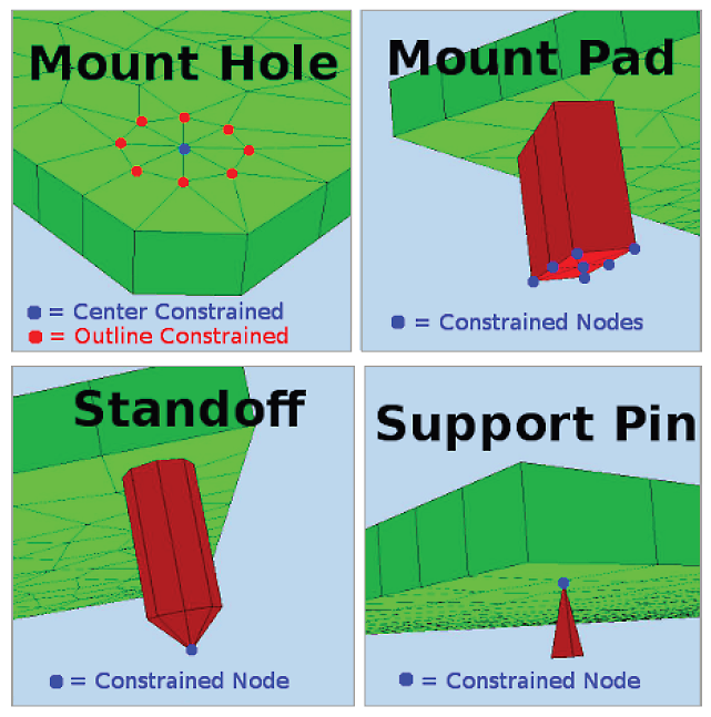
Figure 2b. In Ansys Sherlock electronics reliability prediction software, you can define the type of mounting that you plan to use in that location.
For the certification tests, NewSpace was interested in three mechanical events: random vibration (RV), mechanical shock (MS), and harmonic vibration (HV). Each event was defined by a unique loading profile. For example, the RV loading event related to the rocket launch is shown in Figure 3a, with its associated vibration power spectral density (PSD) statistical profile (Figure 3b).
NewSpace had to consider frequencies between only 20 Hz and 2,000 Hz, which were required for the RV analysis. Sherlock software identified five vibration modes ranging between 991 Hz and 1,829 Hz. This meant that the HV analysis could not be performed, which required vibration modes below 200 Hz, thereby eliminating HV as an area of concern.
For RV, NewSpace considered vibration in all three axes (x, y, and z). Displacement contour plots showed how the RV displacement was dominated by the first natural frequency. (Compare the shapes in Figure 4, with red indicating higher displacement.) While the general performance of the board was good, Sherlock software calculated outright failure of a component in the z-axis vibration. That component was, as expected, the FPGA.
Sherlock software predicted that the FPGA had a 100% chance of failure, with multiple leads exceeding the strain limit. NewSpace identified an almost identical correlation between high lead strain and cracked leads identified in both the experimental testing (see inset photos in Figure 5) and simulation results.
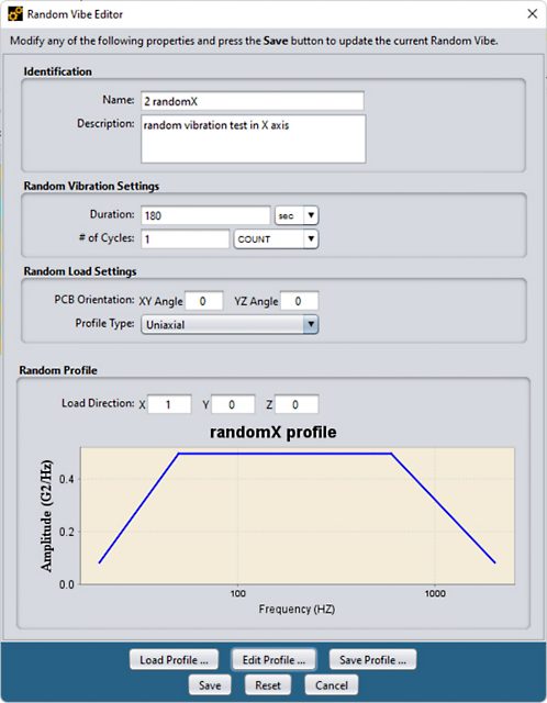
Figure 3a. the random vibration (RV) loading event related to the rocket launch
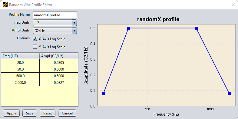
Figure 3b. an associated vibration power spectral density (PSD) statistical profile
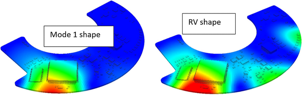
Figure 4. Displacement contour plots show how the RV displacement was dominated by the first natural frequency. (Compare the shapes in the figure, with red indicating higher displacement.)
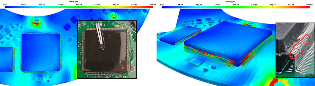
Figure 5. There’s an almost identical correlation between high lead strain and cracked leads identified in the experimental testing.
Combining Solutions To Reduce Failure
To prevent lead failure of the FPGA, NewSpace tried a combination of two solutions. The first was to add additional mounting points to the components’ PCB to increase the frequency of its resonant mode so that it fell outside the damaging vibration spectrum. Secondly, the chassis was stiffened using a process called “staking” to increase its resonant mode and reduce the deflection of the chassis under vibration. (See the yellow ellipses in Figure 6b.) Staking refers to using resin or adhesive to glue components together or to the board. The adhesive anchors the chip to the board surface and takes some of the load off the leads.
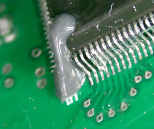
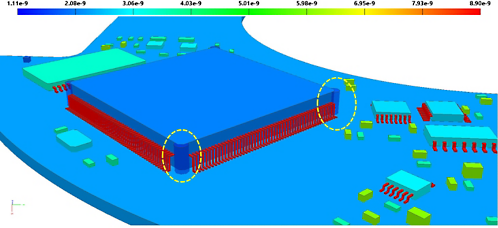
Figures 6a and 6b. To try to prevent lead failure of the FPGA, NewSpace looked at adding staking to the corners of the FPGA.
The combination of mounting and staking solutions was optimized by performing Mechanical software’s RV analysis on the chassis and PCB and assessing both the total deflection of the chassis and fatigue lifetime of the leads. As expected, NewSpace saw an improvement in the performance of the leads under vibration. Sherlock software’s lifetime prediction indicated that some leads would, unfortunately, still fail, but these failures would be fewer in number than before and would occur only after 2.3 years — significantly longer than the previous simulation indicated. After running a few more simulations, NewSpace was able to produce an FPGA with 100% reliability over the lifetime of the satellite, which was the original target.
For more details of the capabilities of Sherlock software, visit our Ansys Sherlock software page.
Author: Written by Evan Smuts, Senior Engineer from Qfinsoft and Shane Martin, Mechanical Design Lead from NewSpace Systems.
Related Posts